Final Report - The Columbia River Interstate Bridge
THE
COLUMBIA RIVER
INTERSTATE BRIDGE
FINAL REPORT


THE COLUMBIA RIVER INTERSTATE BRIDGE
As seen from Hayden Island, looking toward Vancouver. Length 3,530 feet. Taken at time of high water.
FINAL REPORT
The Columbia River Interstate Bridge
Vancouver, Washington to Portland, Oregon
FOR
Multnomah County, Oregon
Clarke County, Washington
BY
JOHN LYLE HARRINGTON AND ERNEST E. HOWARD
CONSULTING ENGINEERS, KANSAS CITY, MO.
Copyright, 1918
by
JOHN LYLE HARRINGTON
AND ERNEST E. HOWARD
THE COLUMBIA RIVER
INTERSTATE BRIDGE COMMISSION
PERSONNEL
From November, 1913, to January, 1915.
Rufus C. Holman, Chairman;
W. L. Lightner,
D. V. Hart,
Governor Oswald West,
Commissioners for Multnomah County.
A. Rawson,
W. S. Lindsay,
S. N. Secrist,
Commissioners for Clarke County.
W. N. Marshall, Secretary.
From January, 1915, to January, 1917.
Rufus C. Holman, Chairman;
W. L. Lightner,
Philo M. Holbrook,
Governor Jas. B. Withycombe,
Commissioners for Multnomah County.
A. Rawson,
W. S. Lindsay,
John P. Kiggins,
Commissioners for Clarke County.
After January, 1917.
Rufus C. Holman, Chairman;
Philo M. Holbrook,
A. A. Muck,
Governor Jas. B. Withycombe,
Commissioners for Multnomah County.
M. E. Carson,
Abe Miller,
John P. Kiggins,
Commissioners for Clarke County.
Legal Advisers: Walter H. Evans, Arthur A. Murphy, James O. Blair, L. M. Burnett.
| August 12, 1913 | Clarke County, Washington voted bonds for construction. |
| November 4, 1913 | Multnomah County, Oregon, voted bonds for construction. |
| Novomber 29, 1913 | The Columbia River Interstate Bridge Commission organized. |
| December 29, 1913 | Commission selected Engineers. |
| December 29, 1913 | Commission directed Engineers to prepare preliminary plans and to make a report recommending a location for bridge and approaches. |
| January 31, 1914 | Bill authorizing construction passed Congress. |
| March 26, 1914 | Engineers completed preliminary studies, and recommended location of structure. |
| March 30, 1914 | Commission adopted report and located structure. |
| April 13, 1914 | Engineers made application to Secretary of War for permit for construction. |
| April 20, 1914 | Public hearing of War Department to consider proposed plans. |
| June 12, 1914 | Tentative approval of plans given by Secretary of War.
Progress delayed by financial disturbance due to commencement of war in Europe. |
| November 1914 | Clarke County sold $250,000 bridge bonds. |
| November 9, 1914 | Multnomah County sold $250,000 bridge bonds. |
| December 1914 | Clarke County sold $250,000 bridge bonds. |
| December 14, 1914 | Multnomah County sold $1,000,000 bridge bonds. |
| January | 11, 1915, | Engineers presented final detailed plans and specifications. | ||||||||||||||||||||||||||||||||||||||||||
| January | 11, 1915, | Commission adopted plans and specifica— tions and ordered work advertised. | ||||||||||||||||||||||||||||||||||||||||||
| February | 23, 1915, | Commission received bids for all principal construction work. | ||||||||||||||||||||||||||||||||||||||||||
| February | 27, 1915, | Commission awarded contracts for principal construction work. | ||||||||||||||||||||||||||||||||||||||||||
| March | 6, 1915, | Actual construction formally started. | ||||||||||||||||||||||||||||||||||||||||||
|
Engineers presented and Commission adopted plans and specifications for Derby Street approach embankment. Commission received bids for Derby Street approach embankment. Commission awarded contract Derby Street approach embankment. Final approval of plans given by Secretary of War. Engineers presented and Commission adopted plans and specifications for pavement of approach embankments. Commission received bids for pavement of approach embankments. Commission awarded contract for pavement of approach embankments. Commission awarded contract making purchase of materials for lighting system. Commission awarded contract for constructing lighting system. Bridge formally opened to trailic. Engineers rendered final estimate for last contract. CONTENTS PAGE
ILLUSTRATIONS PAGE Columbia River Interstate Bridge _ _ _ _ _ _ . _ _ . _ . _ _ . _ _ _ . _ . . _ _ _ - Frontispiece Vancouver End of Columbia River Bridge . . _ _ _ . _ _ _ _ _ _ _ _ _ _ . _ _ _ _ _ . _ _ _ --12 Oregon Slough Bridge as seen from Hayden Island __________________ __‘12 Columbia River Bridge as seen from Vancouver _ _ _ _ _ _ _ . _ _ . . . . _ _ . _ . _ -_19 Drawing, Floor Construction of Truss Spans _______________________ _-23 Lift Span Operating Machinery Assembled in.Shop _________________ __24 Columbia River Bridge as seen from Vancouver ____________________ --26 Drawing, Details of Typical Pier _________________________________ --28 Construction of Union Avenue Approach Embankment _ . . _ . _ _ _ , _ . . _ __30 Pile Driver Equipment used in Building Piers _ _ . _ _ _ _ _ _ . _ _ . _ _ _ _ _ _ _ _ __34 Manufacturing the Steel. Trusses Assembled at Bridge Shop __________ _-36 Building the Piers, Removing Cofferdam ___________________________ __37 Erecting Through Truss Spans on Shore _ _ . . _ _ _ _ . , _ _ _ _ _ _ _ _ _ _ _ _ . _ _ _ _ __39 Truss Spans on Launching Ways Ready for Moving _________________ ..40 Moving Completed Span Across River on Barges . _ . _ _ . _ . _ . _ _ _ . _ _ . _ . _ _-41 Embankment Construction, Bulkheads and Methods of Deposit _ _ _ _ _ . . _-43 Completed Embankment along Union Avenue Approach _ _ _ _ _ _ _ _ . _ _ _ _ __44 Opening Day Columbia River Interstate Bridge _ _ . _ _ _ . _ _ , _ _ _ _ _ _ _ _ _ _ _ -_(il 10  These inscriptions on bronze tablets are on the entrance columns of the bridge.  (Upload an image to replace this placeholder.) VANCOUVER END OF COLUMBIA RIVER BRIDGE. THE OREGON SLOUGH BRIDGE. As seen from Hayden Island, looking toward Portland. Length 1,110 feet. The Commissioners of Multnomah County, Oregon. The Commissioners of Clarke County, Washington. Gentlemen: The Columbia River Interstate Bridge between Vancouver, Washington, and Portland, Oregon, is completed and in service. We now respectfully submit our final report upon all the principal matters pertaining to its construction. Beginning with our report of March 26, 1914, recommending the adopted location of the bridge and its approaches, we have made many reports to you, including regular weekly reports showing the progress of the work included under each contract, monthly reports and estimates showing the amounts earned by each contractor, reports relating to tests and inspection of materials and workmanship, and various special reports on rights of way, franchises, operation, and similar matters. These are all in your files and available for reference; hence their details will not be repeated; but this report will be confined to the more important engineering and business features of the whole project, including your own actions. The efficient and harmonious working of the Columbia River Interstate Bridge Commission has been largely responsible for the success and celerity with which the work has been carried out. Although composed of the Commissions of two counties situated in different states, having different laws and different interests, differing greatly in wealth and population, and contributing different sums of money, we have found the Commissioners, while jealous of the rights and tenacious of the prerogatives of the community each represented, always fair and reasonable and ready to find some common equable ground for adjusting differences so as to permit the work to go forward. The eminently satisfactory progress and conclusion of the work could not have been attained except for the promptness of the Commission in deciding the many questions presented, and for the unwavering firmness with which the Commission adhered to a position adopted or a policy determined. We have been highly gratified to have the Commission adopt, we believe without exception, our every recommendation. The care and attention to detail which marked the execution of the design and other technical features are evident in the completed structure, and are also indicated in the financial statement. Beginning with an amount of money insufficient, according to early reports, even for a bridge with a 24-ft. roadway and one approach on the Oregon side (main bridge, $1,660,700; Oregon approach, $420,000), the design both of substructure and superstructure proved to be so fitting and economical and conditions for construction according to these designs so favorable, that the bridge was completed with a 38-ft. roadway, with concrete floor, wholly fire-proof, and with two approaches on the Oregon side, within the funds ($1,790,000) and with a balance of the original fund left with each county (totaling $56,000). But we have attempted to serve you broadly; not alone along technical lines, but in the administration and in the general business of buying a bridge and getting full value for the money spent; in the study of the broad and general needs of the public for transportation facilities, which was a large factor in determining the recommendation for the location of the bridge and approaches, in assisting with negotiations for the acquirement of the rights-of-way and other properties; in drafting tentative franchises for street railway operation; in the determination of tolls to be charged; in arranging a scheme of organization for the operating department, and in the general problems of administration. We have tried always to give the same careful and detailed attention to every question submitted to us as we have to essentially engineering problems. In this connection, we would like to add, that never in a long experience of similar undertakings have we known more sympathetic, broad-minded and intelligent co-operation from a legal department than you have received and we have enjoyed at the hands of Mr. Walter H. Evans, District Attorney, and his associates. The Columbia River Interstate Bridge is a great public work carried through with intelligence. economy and efficiency. It should always be a source of gratification and pride to the members of the Columbia River Interstate Bridge Commission, for it cannot but long be known as a monument to their public service. Respectfully submitted, John Lyle Harrington, GENERAL STATEMENT The Columbia River Interstate Bridge is in some respects unique as a public work; unique in the persistence and unanimity of the people of Clarke County and Multnomah County in providing for its construction; unique in the celerity of the public officers in organizing and pushing forward with the work; unique in the rapidity of construction; unique in the fact that the entire work originally contemplated and a complete additional approach were constructed within the money provided; and unique in proving to be a paying investment, with a constantly increasing income. It is also the first and the only highway bridge over the Columbia River from far above the mouth of the Snake River to the Pacific Ocean. For many years the Columbia River was crossed only by ferries. At length a railroad bridge was built at Vancouver, and one or two up the river, but the highway traffic was still confined to the ferries. With increase of population and of travel, and the widespread and growing realization of the need for improved highways, there came to be a general recognition of the necessities for and of the advantages certain to follow the construction of a highway bridge over the Columbia River at Vancouver. Actively advocated by an increasing number of men well known in Oregon and Washington, the demand for a bridge became crystallized. during the early months of 1912, in a movement by the Commercial Club of Vancouver, Washington, and the then Commercial Club of Portland, Oregon, which finally resulted in the enactment of laws by the States of Washington and Oregon permitting Clarke County, Washington, and Multnomah County, Oregon, to provide funds by voting bonds and to join in the construction of a bridge. (Laws of Wash1ngton 1913, Chapter 56, page 168; Laws of Oregon 1913, Chapter 349, page 701.) Active campaigns for immediate action under these statutes were conducted by the two organizations and received hearty endorsement from the citizenship, for on August 12, 1913, Clarke County voted overwhelmingly for the issuance of $500,000 of bonds, and on November 4, 1913, Multnomah County followed suit by providing for an issue of bonds of $1,250,000. The Acts provided that the work should be carried forward by the regular County officers, except that in Oregon the Governor of the State was to act with the County Commissioners for certain purposes. The two Boards of County Commissioners met in joint session November 29, 1913, and for convenience of action organized themselves into the Columbia River Interstate Bridge Commission, with Rufus C. Holman as permanent chairman, and with VV. N. Marshall, auditor of Clarke County, as seeretary. A simple arrangement that all acts of the joint Commission would be ratified in due order by each separate Board made it possible for the two Boards to act in unison. The personnel of the Commission throughout the whole work is given on a preceding page. The Commission took up as its first action the selection of engineers for the work, and, after a month of investigation and consideration, on December 29, 1913, your Engineers were chosen from the dozen or more applicants. This prompt and timely action in employing engineers had much to do with the success of the work. for the Engineers found the Commission with open minds, without preconceived ideas or set notions, and were able to undertake the solution of the problems from a purely scientific standpoint. The Commission directed the Engineers to proceed immediately with the necessary surveys and studies, and to make a report recommending a location of the bridge over the river and for an approach in Vancouver and one on the Portland si(le. After two and a half months spent in making surveys, studies of traffic, estimates of cost, actively assisting in securing options for rights-of-way for each location, and after considering in every way four possible approaches on the Portland side and four in Vancouver, your Engineers reported their findings and recommended locations on March 26, 1914. In order to determine definitely the costs of right-of-way for each approach the Commissioners in Clarke County and Mr. J. Fred Larson, acting for Multnomah County, had secured written options on the lands required for all approaches at definite prices. Definite and complete cost comparisons could thus be made. After a few days of consideration, with public hearings for citizens who wished to be heard concerning approaches, your Commission adopted the Engineers' recommendations and fixed the bridge approaches to be at Union Avenue on the Portland side and at 'Washington Street on the Vancouver side, subject to the conditions that the city of Portland should extend Union Avenue to the city limits and also should secure from the Portland Railway Light and Power Company an adequate relcase'of their exclusive rights over a certain strip of land which that company owned in the street, and to provide for "common user" over the tracks of the company in that strip. The city of Portland later fulfilled both of your conditions. The Engineers had, in the meantime, been occupied with preliminaryborings and soundings for the several bridges. As soon as the locations were fixed these investigations were pushed to conclusion and preliminary plans for the bridges over the main channel of the Columbia River, over Oregon Slough and over Columbia Slough were prepared and copies were submitted to the Secretary of War with applications for permits for construction. The customary public hearing before the Engineers of the War Department was held in Portland on April 20th, and on June 12th, 1914 tentative approval of the plans was secured from the Secretary of \Var. The preparation of final detailed plans and specifications was immediately undertaken. The Legal Department had been proceeding during the same months and had taken the necessary steps by certain friendly suits to establish the validity of the bond issues to such good purpose that on July 14, 1914, the last necessary action was concluded by a favorable decision of the Supreme Court of Oregon relative to the Oregon bonds. The financial disturbance caused by the beginning of the war in Europe in August, 1914, made it impracticable to dispose of the bonds immediately. but in November each County satisfactorily placed a portion of its bonds, and preliminary funds were secured. Upon advice of your Engineers, however, that in the still unsettled condition of the money market and the uneasiness of contractors in becoming largely involved unless all funds were provided, the remaining bonds were placed in December, 1914, so that the entire funds were on hand to pay for the work. The correctness of the Commission's action in this matter was thoroughly demonstrated when the bids for the work were received, for they were unexpectedly and agreeably low. On January 11, 1915, the final detailed plans and specifications for the construction were submitted by the Engineers, were approved and adopted by the Commission, and advertisements for bids ordered. On February 23, 1915, bids were received from twenty-four contractors. Acting on previous instructions from your Commission, and as later described, your Engineers had prepared complete plans for two different designs for the main structure over the Columbia River channel, one containing a movable span of the swing type, and the other one of the vertical lift type. The lowest combination of bids received for each design showed a saving by the use of the vertical lift type of movable span. amounting to $70,013.60. On this showing, your Commission on February 27, 1915, adopted the design contain~ ing that type and awarded contracts for the construction of the bridges as follows: Contract No. 1-To the United States Steel Products Company. of San Francisco. for the manufacture of the superstructure metal work of the Columbia River bridge. Contract No. 2—To Porter Brothers. of Portland. for the erection of the superstructure metal work of the Columbia River bridge. Contract No. 5—To the Northwest Steel Company, of Portland, for the manufacture of the superstructure metal work of the Oregon and Columbia Slough bridges. Contract No. 6—To Porter Brothers, of Portland, for the erection of the superstructure metal work of the Oregon and Columbia Slough bridges. Contract No. 7——To the Pacific Bridge Company, of Portland. for the foundations of the Coltunhia River bridge. Contract No. 9—To the Pacific Bridge Company. of Port» land. for the foundations of the Oregon and Columbia Slough bridges. Contract No. 10—To the Tacoma Dredging Company, of Tacoma, \Vsshington. for the approach ernbankments. Contract No. 11—To the \Varren Construction Company, of Portland, for the concrete deck slabs and paving on all the steel bridges. The bids received at this time for the paving of the embankmenls were rejected owing to the small number of bids and the feeling that those received were unduly high on account of the length of time, about eighteen months, that must elapse before work on this contract could be started. The bids received on all of the contracts awarded at this time were considerably lower than anticipated. so that there remained sutllcient [units from the proceeds of the bond issues for the construction of impmvements not included in the original plans. The largest of these was the approach embankment to the bridge from Derby Street, which serves a section of Portland distant from Union Avenue, and for which there had been an insistent demand from the inception of the project. Your F.ngi« ncers submitted plans and specifications for the construction of this approach embankment on April 2, 1915. at which time they were approved by your Commission and the advertisement for bids ordered. Bids were received on April 2ti. 1915, and on April 30. 1915. contract was awarded to the Standard American Dredging Company. The awarding of the contract for the paving of embankmenls was delayed partly from caution and partly by causes beyond the control of your Commission or your Engineers. Your Engineers deemed it advisable to wait until after the high water of 1916 in order to observe the effects of such high water on the ombankments. and so as not unnecessarily to subject permanent pavemont to possible settlements which might occur to 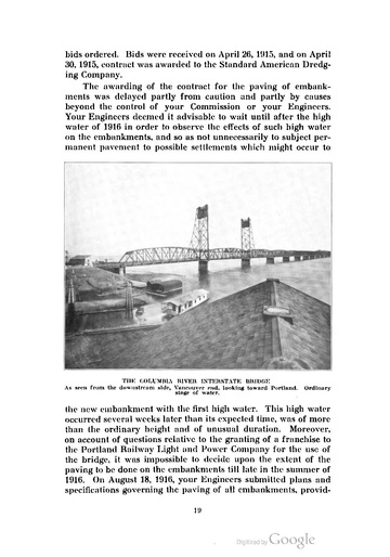 (Upload an image to replace this placeholder.) the new embankment with the firs! high water. This high water occurred several weeks later than its expected time. was of more than the ordinary height and of unusual duration. Moreover, on account of questions relative to the granting of a franchise to the Purtlaml Railway Light and l'uW'er Company for the use of the bridge. it was impossible to decide upon the extent of the paving to be done on the embankmenls till late in the summer of 1916. On August 18, 1916, your Engineers submitted plans and specifications goveming the paving of all embankmcnts, providing for the taking of bids upon various types in order to secure the fullest competition, and providing also for various widths of pavement pending the settlement of franchise matters over the approaches and the decision of your Commission as to the paved width to be provided. Bids were received on September 19, 1916, and agreement having been reached meanwhile with the Portland Railway, Light and Power Company, whereby it would use the Columbia River bridge and Vancouver approach, but not the Union Avenue approach, your Commission decided to pave a 38-ft. width over Hayden Island, 30 ft. on the Union Avenue approach south of Oregon Slough and 18 ft. on the Derby Street approach. Contract was awarded on September 20, 1916, to the Warren Construction Company for bitulithic pavement on broken stone base for Union Avenue approach, macadam for Derby Street approach and bitulithic pavement in Vancouver. The awarding of this contract provided for the last item of construction with the exception of the lighting system. Contracts for the furnishing of the main items of material for this system were awarded on October 27, 1916, to the United States Steel Products Company and the Pacific States Electric Company, and on March 6, 1917, contract for the installation of the lighting system was awarded to Nelson & Brown. The various contractors assembled materials and equipment immediately after thesigning of their respective contracts, and construction proceeded as rapidly as the river conditions would permit. Although practically all of the contractors were working at the same time, the whole work progressed smoothly and substantially without friction or interference under the capable and efficient supervision of the Engineers' representative in charge, Mr. Frank M. Cortelyou, Resident Engineer. Following the signing of the contracts, your Commission was occupied with the final acquirement of the lands for right-ofway. with consideration through committees of franchises and of matters relating to management of the property after the conStruction should be finished, with the determination of the income required for proper operation and of toll charges necessary to provide it. Mr. Evans concluded that certain special legislation was desirable in Oregon to simplify the control of the property and the passage of suitable bills by the Legislature of the State was secured. The Commission met from time to time to receive reports of progress from the Engineers and to approve for payment the monthly payment estimates to the contractors for the work done. The public necessities made it appear desir able to the Commission to provide for traffic at the earliest date possible, and the bridge was opened to traffic as soon as the pavement of the roadways had been completed, and several weeks before the last of the work, comprising the finishing touches to the structure, had been carried out. The following pages include a general description of the bridge and approaches, and information concerning the loadings for which the bridge is designed; a description of some of the interesting construction features, a tabulation of the quantities in the structure and of the costs and classification of costs; a summary of the franchise provisions of the Portland Railway, Light and Power Company; and, finally, suggestions for maintenance and operation of the structure, which should come to the attention of the Commission. GENERAL DESCRIPTION OF BRIDGE[edit]The Columbia River Interstate Bridge and Approaches extends across the valley of the Collunbia River from the city limits of Vancouver, \Vashington, to the city limits of Portland, Oregon, a distance of three and a quarter miles, and includes about 5,000 lineal ft. of steel bridge structures and 12,000 ft. of embankment, in addition to which there is a secondary embankment on the Oregon side about 6,000 ft. long. The bridge and approaches provide a roadway for street traffic and tracks for street cars, and over steel structures a sidewalk. At times of extreme flood, the high water covers the entire three-mile width of valley and extends from Vancouver to the city limits of Portland. The Columbia River at the bridge site is 3,500 ft. wide, with a maximum depth of 30 ft. at extreme low water and with variation from extreme low to extreme high water of 33 ft. The water rises each spring to about 20 ft. and about once in four years to 25 ft. So far as known it has reached 33 ft. only once. The bed of the river consists of sand, with small amounts of gravel, extending to great depths. At the north shore very compact cemented gravel is found a few feet below low water, dropping ot't' to 100 ft. below at about 700 ft. from the north shore. Over the remainder of the river only sand with some gravel was found to depths of more than 100 ft. The Oregon Slough forms an important secondary channel, particularly for flood conditions. It is about 1,000 ft. wide, and 25 ft. deep, and is separated from the main river by an island about 1,500 ft. wide. The U. S. Government has built a dyke some distance above the bridge site and the island to divert practically all of the low water flow down the main channel of the river, the top of the dike being about 6 ft. above low water. The bed of this slough is principally sand. The Columbia Slough provides some drainage near the Oregon side of the valley, is about 300 ft. wide and 20 ft. deep at low water. The bottom is of very soft clay and sand; hard and compact gravel is found about 80 ft. below low water. The average elevation of the ground across the river valley is from 12 to 15 ft. above low water, so that much of it is inundated at every high water period. The roadway is 38 ft. wide between curbs on the steel spans, 38 ft. wide between rock shoulders across Hayden Island, 30 ft. wide on the balance of the Union Avenue approach and 18 ft. wide on the Derby Street approach. Over the steel spans there is one sidewalk 5 ft. wide. Double track street car tracks for both standard and narrow gauges are placed in the middle of the roadway on the steel structure, spaced 10 ft. 815 ins. center to center. The vertical clearance on the truss spans is 21 ft. 6 ins. The roadway on the steel structures across Hayden Island and on the Union Avenue approach is paved with bitulithic pavement and on the Derby Street approach with macadam. The bridge over the Collunbia River consists of a series of through riveted truss spans with curved top chords; three spans 275 ft. long and ten spans 265 ft. long. together with a small deck girder span at the Vancouver end, making a total length of 3,531 ft. 57/3 ins. between end shoes. Provision for navigation on the river is made by a vertical lift span. The central of three 275 ft. spans is arranged to lift between towers on the other two, so as to afford a channel 250 ft. wide at right angles to the current of the river and 150 ft. high above ordinary high water. For the through spans the trusses are spaced ~11 ft. center to center, with the roadway between and the sidewalk beyond one truss. The floor is a reinforced concrete slab 51,4 ins. thick, and the sidewalk is also of reinforced concrete. The arrangement of the beams and of the concrete slab for the floor merits attention, as it is new and original. Between usual floor beams are longitudinal stringers spaced about 9 ft. center to center. On top of the stringers, extending entirely across the roadway, there are 8 ins. I beams spaced about 33 ins. apart. These roadway cross beams are bent to conform to the crown of the roadway, and the concrete slab rests immediately on top of them. The six rails required for the two—gauge, double-track, street car tracks rest immediately upon the roadway cross floor beams and are fastened to them by standard Carnegie steel tie clips. The rails are 7 ins. high, so that there remains a space of 2 ins. in depth above the top of the concrete slabs to the top of the rail for the 2 ins. bitulithic surfacing which forms the pavement. To afford a rail heading which could be removed, if necessary, for access to the rails, or to the bonding, without injury to the roadway slab, the space about 5 ins. wide, on each side of each rail, is filled with concrete to the top of the rails, a flangeway being provided by forming this concrete. A drainage intake with down-spout is placed at intervals of fifty feet along each curb.  Engr. News. This arrangement of floor has the advantage of providing a concrete slab longitudinal in the direction of travel, with comparatively short spans, and of making the supporting steel beams of very simple shop work. Owing to the lateral stiffness of the floor as constructed, the lower laterals of the spans are somewhat lighter than they would be for an open deck bridge. Two fixed ends and two expansion ends of the spans are placed adjacent so as to reduce the number of expansion joints to a minimum. The expansion joints are made of usual type checkered plates supported by and sliding upon metal supports. The corresponding expansion joints for the rails between the spans consists of manganese-steel castings placed beside the webs of the rails, for which one side of the rail heads is planed off. The towers supporting the lift span are of simple construction, riveted throughout, so arranged that the front columns of the towers support all the loads of the lift span and counterweights. The rear columns are bracing members. The lift span is suspended from each of its four corners by sixteen plow steel wire ropes, 2 ins. diameter, which pass up and over cast steel sheaves 12 ft. in diameter, and are attached by a group of equalizing levers to concrete counterweights built around steel frames. These counterweights are of the same weight as the span, as nearly as possible exactly to balance it, so that the work to be done in operation consists of overcoming the friction and inertia, and of lifting the unbalanced portion of the ropes. The span is guided in its ascent and descent by cast steel jaws which engage upon tracks on the towers; at one end of the lift  MANUFACTURING THE STEEL. The machinery for operating the lift span is here seen assembled complete in the shop where it was made, and placed on the structural members. This was done to insure accurate fitting of the parts. The simplicity of the operating machinery is apparent. span these jaws guide both laterally and longitudinally, but at the other end the span is guided only laterally, thus allowing for expansion and contraction of the span and for slight variation in position of the towers. Operation is effected by means of operating ropes, of which there are two pairs at each corner of the span. The operating machinery. which is placed upon the span at its center, just above the roadway clearance. consists of four spirally grooved drums connected by a train of gears to an electric motor. Each of these drums controls the operating ropes for one corner of the span; one pair of operating ropes, leading from the top of the drum, passes over a deflecting sheave at the corner of the span, thence downward, and connects near the bottom of the tower; and a corresponding pair of operating ropes leading from the bottom of the drum passes under a deflecting sheave at the corner of the span, thence upward, and connects near the top of the tower. All of the drums are similarly connected so that when they are operated in one direction the ropes leading to the tops of the towers are wound on the drums, and those leading to the bottoms of the towers are payed ofl', lifting the span by the force exerted upon the corner sheaves. The machinery for operation is thus exceedingly simple, consisting of one transverse shaft extending across the span; one pair of reduction gears in a frame inside of the house, and the back gears upon the motor. An indicator and limit switch is provided by which the current is automatically cut ofi' and solenoid brakes applied to the motors at near the upper and near the lower limit of the run of the span. For ordinary operation there is a hand band-brake. which is equipped with a push button switch, so that when the span is under control the operator can hold off the emergency brake, and bring the span to rest in the control of the hand brake. To provide for emergency operation, instead of the usual hand operating capstan, the span is equipped with a 12-horsepower gasoline engine connected through a speed reducer to the machinery, so that in case of failure of electric current the operator will be able to move the span at slow speed without having to seek outside assistance. There is a manually operated lock at each end of the span in connection with a centering device so that the span may be locked down. The solenoid brakes in connection with the down haul ropes also serve as a lock. Bussbar trolleys are attached to one tower and a sliding contact shoe on the lift span supplies the current to the motors during operation. The operating ropes are attached at the tops of the towers to small drums with worm gear connections so that adjustment for the stretch of the operating ropes can readily be made. When the span is at its upper limit the counterweights are two feet above the floor level and a special arrangement of the trolley wires under the counterweight is made. This consists of swinging frames upon which the trolley wires are fastened, and which are pushed down by the counterweights and returned to position through means of small counter-balances. The rail connections at the ends of the movable span are simple scarfed joints so that the span lifts away from the fixed rails and returns to them without any movable devices. The machinery is designed with great care and nicely. Gears and pinions which operate together are set in cast steel frames so that they could be adjusted and built complete in the shops; the adjustment of parts of the machinery in the field being reduced  THE COLUMBIA RIVER BRIDGE. Near view of Vancouver end showing details of towers and lift span. The moving span weighs about 1,200 tons and each counterweight about 600 tons. Can be lifted to 136 ft. above the tops of the piers. The towers extend to 190 ft. above the roadway. to a minimum. All of the gears are cast steel with cut teeth. There is duplicate motor equipment with either motor of sufficient size to operate the bridge. At the ends of the fixed spans adjacent to the movable span there are provided roadway gates of substantial design to make an effective barrier across the roadway, and these are connected to derailing switches in the street car tracks so that when the gate is closed across the roadway, the derail is thrown. These gates are manually operated and a small steel and concrete cabin is provided at each for the gate tender. Several types of movable spans to provide the necessary channel openings for river navigation were considered, and the matter was narrowed to the selection of either a swing span or a vertical lift span. The Commissioners then desired to receive bids both upon the lift span and the swing span, and plans were prepared for the structure containing both types of movable span. The designs were made according to the same specifications and as nearly duplicate in character as possible. Application was made to the War Department and tentative approval was received for either type of movable span, provided the swing span should have two channels, 200 ft. wide, or the lift span should provide one channel 250 ft. wide, with a vertical clearance of 150 ft. above normal high water. As has been stated, bids were received on both types of structure and it de— veloped that the lowest bid for the bridge, including a lift span, was about $70,000 less than the lowest bid for the bridge, includ— ing a swing span. The lift span was thereupon adopted; not only for the advantage of the lower first cost, but also because, judging from the experiences of Multnomah County in operating bridges of both types, there will be continued advantages in lower cost of operation and maintenance. It is likewise more advantageous for river navigation, in that it provides a channel 250 ft. wide instead of 200 ft. wide, and the channel is not hampered by the long draw protection that would be necessary with a swing span. As the main channel is very close to the Vancouver shore, the necessary draw protection, about 500 ft. long, would have been a serious detriment to the dock frontage ad— jacent to the bridge. The river at the site of the bridge is subject to a certain amount of scour, but inspection of the soundings taken for many years past did not disclose any indication of scour to extreme or unusual depths, although the river, both for some distance up stream and some three miles down stream, is deeper than at this site. The bases of the piers are of concrete enclosed by heavy timber cribs and extend down from 20 to 25 ft. below the river bed. The bases rest upon piles which extend to a depth about 110 ft. below low water. The piles used were about 120 ft. long in single sticks, about 10 ins. diameter at the tip and about 22 ins. at the butt. There is an average of about one pile to ten square feet area of base and in the average pier under the 265 ft. spans there are ninety piles.  (Upload an image to replace this placeholder.) The foundation piles are cut off a few feet below low water so that the upper ends of these piles are imbedded into the concrete of the bases of the piers from 15 to 20 ft. and the piles form a definite portion of the pier. It is evident that even though some unusual scour should, on some extraordinary occasion, extend below the bottom of the base, the pier would still be perfectly stable, owing to the great depth of penetration of the piles and to the rigidity of their upper support. Around each pier base there is an amount of heavy stone rip-rapping, which should be replenished, if necessary, during the next few years. The shafts of the piers above the base are comprised of two cylindrical battered columns, one placed under each pair of shoes. These columns are joined by a vertical diaphragm and by the horizontal coping at the top, both of which are reinforced with steel. This design saves considerable weight which otherwise would require supporting piles and eliminates a large amount of concrete unnecessary for any structural purpose. The occurrence of ice in the Columbia River in sheets or floes of large size is very rare, so that the concrete piers need no special protection of steel or stone facing. The bridges over the sloughs consist of deck spans providing a roadway and floor of the same type and character as previously described, except that the girders are placed 23 ft. apart transversely and a portion of the roadway and the sidewalk is carried on cantilever beams, and there are other minor details of differences, such as necessary trolley poles, etc. These spans rest on concrete piers supported by piles of the same general type as described, for the main river. The piles were sunk to about the same depths, but as the likelihood of scour is much less in the sloughs, the bases are not carried as far below the river bed. The bridge over the Oregon Slough consists of ten deck girder spans 100 ft. long, and one span 115 ft. long, making the total length 1,137 ft. 6 ins. At the present time there is no navigation in the Oregon Slough above the site of the bridge. but as there is possibility of navigation being developed above the site, it was necessary to provide for some type of movable span to furnish the necessary channel openings for vessels. Permission was secured from the War Department to build the structure with all fixed spans at the present time, with the provision that one span should be so arranged that at any time in the future when it may become necessary it can be converted into a movable span by providing towers at each end, and by equipping it with machinery, counterweights, etc., so that it may be operated as a vertical lift span. The 115 ft. span, above mentioned, is arranged for such possible use and will afford a channel 100 ft. wide. This provision and arrangement saves the Commission an expenditure at the present time of about $30,000 and permits a movable span to be provided when necessary without discarding any parts of the present structure and without interrupting traffic. The bridge over the Columbia Slough consists of four deck girder spans of the same general type as described for the Oregon Slough, each 75 ft. long. After the first tentative approval of the plan for the Columbia Slough bridge was given by the engineers of the War Department, the status of this slough was changed so that there has become a remote possibility that it may at some time be considered navigable. It has therefore been agreed that should such development occur, one of these 75 ft. spans will be made to lift in the same manner as above described, providing a clear channel opening of 60 ft. in width. The embankment over Hayden Island has a total length of about 1,480 ft., the embankment of the main approach to Union Avenue has a total length of about 10,500 ft., and the embankment in the secondary approach to Derby Street has a total length of about 5,800 ft. The embankment for the two approaches in Vancouver has a total length of about 500 ft. The embankments across Hayden Island and in the main approach to Union Avenue are 42 ft. wide on top. The embankment of the secondary approach to Derby Street is 40 ft. wide on top and on the Vancouver approaches the widths conform to the widths of the streets occupied. The embankments average about 24 ft. in height and have side slopes of 2 horizontal to 1 vertical. The upstream side of the Union Avenue embankment is protected to the elevation of 20 ft. above low water by concrete slabs laid on the slope of the finished till. These slabs are 4 ins. thick, reinforced with wire mesh and in strips about 8 ft. wide, extending continuously up and down the slope. The overflow  (Upload an image to replace this placeholder.) EMBANKMENT CONSTRUCTION. Union Avenue approach embankment. In the distance the completed embankment can be seen: near at hand the sand is just beginning to be deposited between the lowest bulkheads. The sand was pumped through 24-in. pipe, a maximum distance of 1¾ miles. water, which at times of high water inundates most of the river valley, is largely back water and has no perceptible current, except that caused by its outflow from the river over the land as the river rises and its return flow to the river as the river falls. The time of greatest current with corresponding danger of erosion is at the time when the water is slightly above the height of the river bank, and occurs near the banks. For this reason the concrete protection has been carried up to an elevation of 30 ft. above low water at the ends of the embankment where the high water of 1916 indicated erosion would occur, and at the buried piers has been carried up the full height of the embankment. The area on the slopes not covered by the slabs has been heavily fertilized and sown to grass, and it is expected that compact sod will be secured which will prevent local erosion. Great numbers of evergreen blackberries, a hardy indigenous shrub, have also been set out on the slopes to help in the prevention of erosion. The railing along each side of the embankment is of timber throughout of ample strength and rigidity for the prevention of serious accidents, as has already been proved. The embankment across Hayden Island is more exposed than the other embankment and the Engineers of the War Department required that the slope protection extend entirely over both sides up to an elevation 30 ft. above low water or 5 ft. above normal high water. Owing to the exposed position of the Vancouver embankment, the slope protection there was similarly carried up to an elevation 30 ft. above low water. On the Derby Street approach the high water of 1916 indicated that there was no serious danger of erosion from current except at the ends of the embankment. The Union Avenue approach serves as a protection to the major part of the upstream slope of this embankment, so that the concrete slope protection was provided only at its ends. At each end of the main river bridge there are two entrance columns or pylons of concrete. These are of concrete rather than cut stone or marble because they more fitly represent the simple, straightforward construction of the bridge. They hear bronze tablets which give not only the names of the Commissioners, of the Engineers and of the Contractors, but also certain inscriptions which seemed to your Engineers to represent something of the thought and purpose and ideals of those responsible for the bridge. The inscription from Macaulay seems fitly to represent the purpose of the bridge; the inscription from Ruskin may fairly give the spirit of the builders, your Contractors and your Engineers; that from Carl Schurz is an appeal for remembrance of old ideals of patriotism and of service not unsymbolized by the bridge; and the last from the pen of Richard W. Montague and your Engineers is believed truly to indicate the origin and purpose of the whole endeavor. By permission of the Commission. the Washington chapters of D. A. R. and S. A. R. have erected at the Vancouver end of the bridge as a marker for the old Oregon Trail a simple stone drinking fountain which bears a bronze tablet symbolic of the Spirit of the Trail. The Oregon chapter of the same organiza- tion applied for and received similar permission for the erection of the trail marker at the Oregon end of the bridge. Along both sides of the Union Avenue approach there have been planted roses and Scotch broom and there is similar plant- ing about the entrance columns (seventeen hundred rose bushes and thirty-five hundred Scotch broom plants were set out). With a small amount of care and attention there will soon be added beauty to the substantial utility of the approach embankments. LOADS FOR WHICH THE BRIDGE IS DESIGNED[edit]The attention of your Commission is particularly called to the loads for which the steel portions of the structure were designed. In addition to the actual calculated dead load weight of all parts, and wind loads, provision was made for the follow- ing live, or moving, loads: For the floor system and for girders: On Street Car Tracks—Two 50-ton cars on each track. On Roadways—12-ton motor truck, with special provisions for 24—ton machinery truck or loads per linear foot for each line of traffic varying with loaded length from 812 pounds for 25 feet to 735 pounds for 100 feet. On Sidewalk—600 pounds per linear foot. Impact allowance of 50 per cent is added to all except side- walk loads. F or trusses: On Street Car Tracks—Two 40-ton cars on each track. On Roadways—Loads per linear foot for each line of trailic of about 500 pounds, but varying with the loaded length. For impact allowances the following percentage of each load is added to it: For roadway loading—I = NL21°300 but not greater than fifty per cent.
180 mind not greater than fifty For street car loading—I = per cent. Where I 2 percentage. L = Length of load on bridge producing maximum stress. N = Number of loaded tracks for street car loading, or number of lines of traific for highway load- ing. The above figures will convey to an engineer the permissible loads to be allowed to cross the bridge, but a more detailed state- ment may be of service to the Commission. The bridge was not designed for heavy locomotives or heavy railroad trains. Light trains, of course, can be operated across it with safety. The following limitation, which is included in your franchise to the only railway company now operating, sets out the maximum weights of locomotives, cars and trains which should be per- mitted to operate across the bridge. This should be your guide for granting permission for operation of trains or cars on the bridge: “No car or locomotive of any character weighing in excess of 100,000 pounds gross load, or having any single axle load in excess of 25,000 pounds, shall be pemlitted on the structure; and no cars weighing over 80,000 pounds having a length of less than 20 ft. c. to c. of trucks shall be pemiitted on the structure. Two coupled locomotives or cars shall not weigh in excess of 180,000 pounds gross load; three coupled locomotives or cars shall weigh not in excess of 190,000 pounds gross load nor more than 1,600 pounds per lineal foot; four coupled cars or locomotives shall weigh not in excess of 210,000 pounds, nor more than 1,300 pounds per lineal foot; five coupled locomotives or cars shall weigh not in excess of 230,000 pounds, nor more than 1,200 pounds per lineal foot. Trains composed of more than five loco- motives or cars, or both, shall weigh not more than 1,100 pounds per lineal foot.” The limitation on the roadway of a truck with load totaling 24 tons as given above needs no special explanation. The speci- fications for design employed have not been published and space does not permit their inclusion here, but if the Commission should at any time need information concerning unit stresses and details of design your Engineers will make a supplementary report to give that information. 33 SPECIAL FEATURES OF DESIGN  (Upload an image to replace this placeholder.) BUILDING THE PIERS. Pile-driver equipment used to sink the foundation piles for the glen. The leads are 122 ft. high above the water; the overhang is 2 ft. in front of barge. Equipped with two hoisting engines, two pumps. and 800-H.P. boiler. The marked economy of design came from a thorough study of local conditions and local possibilities for materials, and a fitting of the design and the plans to realize every possible advantage so offered. Possibly nowhere in the world are extreme1y long timber piles available at as low a price as at this bridge site. Not only the river bed conditions already described. but this exceptional facility for securing such piles at reasonable cost was a considerable factor in determining upon the exact type of piers to be used. As has been described, the piles as delivered were single sticks from 120 ft. to 125 ft. long. The specifications described the special equipment, which would be required for sinking these piles, an equipment which proved to be adequate and which accomplished the work, so that the piers as they stand are on piles which on the average extend into the river bed 25 ft. deeper than the bottoms of the piers of the railroad bridge adjacent. The conditions of the Columbia River and of the Oregon Slough were deemed to be particularly f avor— able to the erection of practically the entire bridge by building the spans on shore and floating them to position. The plans were made with this in view and the specifications indicated a preference for this method of construction, although the ordinary method of driving piles and building a temporary trestle on which to erect the steel work was not debarred. Difi'erent con- tractors bid upon different methods, but the bid taking advan- tage of the opportunity for floating the spans into place was $50,000 lower than the lowest bid for erecting on falsework. The exceptional opportunities for constructing the approaches by building permanent embankments by the hydraulic filling process also seemed to your Engineers to fix this as the proper design of structure, for there were abundant supplies of sand in Oregon Slough; cheap electric power, little difficulty with dis- posal of excess water, and cheap lumber for bulkheads; and the specifications so provided for dredging, although no limitation was made on the construction of the embankments by steam shovel and train haul, or other methods. Even though the length of embankment was beyond any precedent for this kind of work that your Engineers could find, the correctness of this decision was also verified when the bids for placing the work by hydraulic dredging were found to be less than two-thirds of the lowest bid contemplating train haul. In the preparation of the plans, minute care was taken to secure every possible advantage which a duplication of items would afl'ord. In the steel work there are, over the Columbia River, only two different truss spans, and the floor systems even of these are duplicated. Over the Oregon Slough there are like— wise two patterns of longitudinal girders with one pattern of floor system, and over the Columbia Slough the girders are all duplicates and the floor system is the same as on the Oregon Slough. It was, therefore, possible for the structural shops to make only a few sets of patterns and to duplicate the parts many times, and this contributed very materially to the low price for manufactured steel. The same duplication was followed as far as possible in the design of the substructure so that the coli'er- dams and forms for the concrete could be moved from one pier to another and used repeatedly. The concrete floor was designed 35 so that the forms would be duplicate and interchangeable. and these were used repeatedly. The details of every part were simplified with the most careful attention so as to make the manufacture and fabrication with as little complexity as possible, with the result that the steel work as delivered, both from the shops of the American Bridge Company and the Northwest Steel Company, was in excellent condition to be readily erected, properly fitting in every part. 50 accurately was the work of the American Bridge Company for the Columbia River trusses carried out that in driving the 17,000 field rivets in the first truss span there were found  MANUFACTURING THE STEEL. View taken at Gary, Ill. All of the trusses were assembled at the shop, as shown lying on the ground here, all the holes for field rivets reamed, and the different members match marked so they could be erected in Vancouver in just the some positions. This insured perfect matching of holes for the field rivets. CONSTRUCTION METHODS AND EXPERIENCES A complete description of the processes of construction will not be attempted, but three features which were of special interest deserve some description. These are (1) the method of building the piers and placing the long piles already described; (2) the erection of the superstructure metalwork by building the spans on shore complete and floating them to the piers; and (3) the construction of the approach embankments by hydraulic dredging. (1) The plant and equipment supplied by the Pacific Bridge Company were unusual in certain respects and peculiarly adapted to the work in hand. Excavation was made by a dipper  (Upload an image to replace this placeholder.) BUILDING THE PIERS. Removing a wooden cofferdam 10 ft. wide. 57 ft. long and 17 ft. hlfi' weld-lug 50 tons in one unit. after the lower onion of the concrete pier had been in Inside It. This comm-3 was used for one 9 er otter another. dredge of the shovel type having a 4 cubic yard bucket. an unusual equipment for such work. With this machine a hole was dredged into the river bed at the site of the pier to the full depth required and large enough to let the sides of the excavation take a natural slope. The timber crib enclosing the base of the pier was partly built on launching ways. floated to position and framed up to full height. A removable cofferdam in one section. used successively on different piers, was then picked up and placed on the crib. the crib sunk to the proper depth in the excavation, and material of the river bed banked around outside to hold it in position. The foundation piles were then sunk by water jets inside of the crib. For the sinking of these piles in the piers the second exceptional piece of equipment was provided, consisting of a pile driver of which the leads were 122 ft. high above the water, and built so as to overhang in front of the barge upon which it was supported about 22 ft. The lowest portion of this overhanging part was about 15 ft. above the water, so that this overhang made it possible to drive all of the piles in a pier from one side of the crib and at any stage of the water. This pile driver was mounted on a wooden scow 32 by 100 ft., 7 ft. deep. In addition to a No. 2 Vulcan Steam Hammer, the driver was equipped with two 4 ins. diameter jet pipes, 110 ft. long, connected by flexible hoses to the pumps. Water was supplied to the jets by two 12 ins. x 18 ins. x 10 ins. compound duplex pumps, each having a capacity of 1,000 gallons per minute. One four-drum hoisting engine and one two—drum hoisting engine supplied the power for handling the equipment and were all furnished steam from an 800-horsepower boiler. A pile would be set in place on the river bed and the jets discharging water with nozzle pressure of from 100 to 150 pounds per square inch played at its point. The jets thus bored a hole into which the pile slid down with the help of the steam hammer. It was an ordinary experience for one of these long piles to be sunk entirely to place within ten minutes after being placed in the leads and as many as 25 piles were driven in one day. After the piles had been driven, the sand, gravel and other material washed up inside the crib by the driving was removed down to the bottom of the base and the base was filled by depositing concrete under water, through a tremie, up to within a couple of feet of the pile cut-ofl'. When this concrete had thoroughly set the crib was pumped out, the piles sawed off and the remainder of the concrete for the base placed in the open. Wooden forms for the shafts of the piers of usual character were then built up to above water level and filled with concrete. The one-section cofi'erdam was then lifted 011', to be used on a succeeding pier, and the remainder of the shaft forms built up and concreted. The river bed surrounding the pier could then be properly leveled up and adequate amounts of large rip-rap stone placed about the pier. This difficult foundation work was carried out by Mr. C. F. Swigcrt of Portland, under his personal direction. (2) For the erection of the superstructure metal work of the Columbia River Bridge the Contractor arranged a material and erection yard in Vancouver. Each span was erected parallel to the river on low falsework well back on the bank of the river. Launching ways were built at right angles to the erection falsework and extended from it out into the river into deep water at about the same height as the piers. These were 270 ft. long  (Upload an image to replace this placeholder.) ERECTING THE SUPERSTRUCTURE METALWORK.
and each consisted of a heavy trestle with bents of piles spaced 5 ft. centers of live piles each with suitable caps. On each were four timber stringers 10 ins. by 20 ins. and on top of the stringers eight lines of 2% ins. steel rails. Each span was erected by derrick cars operating on tracks running along each side of the falsework, and after all of the steel was in place and all of the rivets driven, the span was rolled out on the launching ways, using 22 rollers 11,42 ins. diameter under each corner. Successive spans were thus built on the same falsework and rolled out on the same launching ways. For moving the spans from the launching ways to the piers. four barges were used. on which fulsework of timbers was built up to a proper height so that with a span on the barges the shoe of the span would be a few inches above the tops of the piers. When ready for moving. water was pumped into the seows supporting the fnlsework and they were floated underneath the span between the launching ways. Blocking was then placed between the falsework on the scows and the under part of the span so as to provide proper bearing, and the water pumped out of the scows, so lifting the span 011' the ways. The span floating on the barges was then towed out to position over the piers by  (Upload an image to replace this placeholder.) ERECTING THE SUSPERSTRUCTURE METALWORK. View of launching ways and spans ready to be transported as seen from the river. One of the barges for carrying the span may be seen to the left. steamboats and tugs and water was pumped into the scows, lowering them and bringing the span to rest on the piers, and finally entirely releasing the seows, which were then taken back for another span. The erection of the towers and other portions of the structure were by methods not unusual in steel erection, except that for the Oregon and Columbia Slough spans the material was all floated near to position on scows and erected from them. The economies afforded by this method of erection have already been mentioned. The work was carried out under the personal direction of Mr. Gay Willard. (3) The Tacoma Dredging Company moved its hydraulic dredge to the bridge site. installed pipes and pumped its first sand on June 9, 1915. By November 20th of the same year all of the embankment of the Union Avenue approach south of Oregon Slough had been placed, so that the placing of this material, which had a total net volume of 821,000 cubic yards. occupied 160 days. or a net average of about 5,000 cubic yards a day.  (Upload an image to replace this placeholder.) ERECTING THE SUPERSTRUCTURE METALWORK. Transporting one of the span from the launching ways on shore to its piers by floating. The span is 275 ft. long and weighs 500 tons. Its lowest part is about 35 ft. above the water. Four barges and two steamboats, besides tugs. were used for moving. The material was excavated from the Oregon Slough by means of a suction dredge with a cutting head and was transported to place by being pumped through a line of pipe 24 ins. in diameter. The operation was by electric power and the main pump on the dredge was operated by two 500-horsepower motors. The pump was of capacity to give a discharge through the 24-inch pipe at a velocity of 12 to 15 feet per second. Operation continued 24 hours per day during the time specified and the dredge was actually running about 14 hours per day. For periods of a few hours at a time the dredge pumped as much as 1,000 cubic yards per hour. There was, of course, a very considerable run-off of sand from the embankment, as well as a certain amount of fine material which flowed away with the waste water, and it is estimated that about 250,000 cubic yards more than the above net amount was transported. The discharge pipe line was extended to a length of about 5,500 ft., working from the dredge alone. For the greater distances a booster pump was installed in the line to give additional impetus. This pump was operated by a single 1,000-horsepower motor operating with considerable overload. The dredge and booster pump together transported through a maximum length of 9,000 ft. of pipe. Such long distance dredging into an embankment so comparatively narrow and high is believed to mark a record for work of this character. The pipe was of the ordinary riveted variety with slip joints made of 7 gauge material on the pontoons and of 10 gauge material elsewhere. It was moved about by teams and wagons. The embankment was formed by the use of timber bulkheads. These were built of 6 by 8 ins. posts, about 10 ft. centers, ' supporting 2 by 12 ins. sheathing, surfaced both edges. The sides of the embankment were built up by these means in steps 8 ft. wide and 4 ft. high. The first bulkheads were placed upon the natural ground surface by driving in the 6 by 8 ins. posts with a hand maul and setting the lower plank into a small trench so that the bulkhead sheathing extended perhaps 8 to 12 ins. below the ordinary ground surface. When the sand had been filled in about the top of such first bulkheads, posts for succeeding bulkheads were set in place and the lower plank placed so that it extended about 12 ins. below the top of the first bulkhead below. These posts were tied back into the embankment by 2 by 6 ins. ties spiked on near the top of each post and extending back to a short post, in front of which were placed a few pieces of lagging to offer additional resistance. The pipe was laid to discharge into the middle of the embankment and was carried forward from the river, bringing the embankment up to the final grade and working away from the dredge. A framework of baffleboards was placed under the discharging end of the pipe, causing the water to spread out and spill over the ground below and run forward, distributing the different sizes of material as the velocity decreased. At some convenient low point there was provided an outflow down the side of the embankment, for which the steps of the embankment were paved with plank to prevent wash. The methods of constructing the bulkheads and of the discharge arrangement are clearly shown by the accompanying photographs. After sections of the finished embankments became thoroughly drained as the work proceeded. the posts of the bulkheads were cut away and the planks removed and carried forward for repeated use. Parts of the posts and of the 2 by 6 ins. ties therefore remain in the embankment. The finishing of the slopes was done by hand with shovels, and the successive steps were so located that the upper corner of each step filled into the lower corner of the step below, to provide the proper slope. The actual pumping and transportation of the sand in  (Upload an image to replace this placeholder.) EMBANKMENT CONSTRUCTION. Nesr view of Unlon Avenue a preset: emboth while deposltl sand b an at; tbs-ouch 24-ln. tpe. The w]:st bulkheads were removed ear puma: '12; s Inge slopes. hed. and the e almost! dressed to smooth the hands of these Contractors were the simplest parts of the work, and they found it economical to permit a very considerable wastage of material where such wastage saved in the construction of bulkheads. This work was carried out under the personal direction of Mr. Edward Simpson of Tacoma. Vice-President of the Tacoma Dredging Company. The secondary approach to Derby Street was constructed in a similar manner by an electrically operated suction dredge with 20-inch diameter pipe equipment. The maximum distance the material was carried was about 6,500 feet.  (Upload an image to replace this placeholder.) EMBANKMENT CONSTRUCTION. There were several slips or subsidences of the supporting land caused by placing the great weight of the embankment on it, but they were less in number or in aggregate amount than had been anticipated or suggested by the specifications. The subsidences of the land probably average less than one foot over the whole area of the embankments. but in three locations there were considerable subsidences. of which two instances required merely the reconstruction of some bulkheads and the placing of additional material. The third and most serious was a subsidence combined with a slide at the south side of the Columbia Slough, which, although causing only comparatively small loss of embankment, destroyed the practically finished pier No. 27 in the slough. The weight of the wet sand embankment on the soft, oozy bottom of the slough and on the somewhat slippery bank was too much for the stability of the supporting material, and a part of the bank and the new sand just placed slid out into the slough, causing the damage to the substructure. The buried pier "F" on the land side of the slip was not disturbed by the movemovement, and the similar construction on the opposite side of the slough had been completed and was standing satisfactorily. Additional embankment was placed for the portion which had subsided. The pier was then repaired and replaced with additional foundation piles and new concrete, and the entire construction was finished without further slides or disturbances. The pavement construction was somewhat unusual. As the embankments were practically pure sand, ordinary methods of preparing the subgrade could not be followed. The specifications provided that the Contractor might either add clayey material to the sand surface in such amounts that the subgrade could be formed and rolled, or else merely shape up the sand to correct surface and then pour on enough water to pack the sand similar to a wet sand beach, hard enough to deposit and roll the stone, keeping the sand "continuously and thoroughly wet, hard, and firm until and during the placing of broken stone or concrete." The latter alternative was followed, but the broken stone base was rolled only lightly, as continued rolling caused the stone to work to the sides, and after the base had been shaped up by the light rolling a cushion coat of bitulithic paving mixture was applied and the whole thoroughly rolled. The placing of the bitulithic surfacing by standard methods followed immediately.
FRANCHISE TO PORTLAND RAILWAY. LIGHT & POWER COMPANY The matter of Franchises for the operation of cars over the bridge came to the attention of your Commission soon after the construction of the bridge was started. At your meeting of April 30, 1915, you appointed an advisory committee on franchises, consisting of District Attorney Walter H. Evans of Multnomah County, Prosecuting Attorney James O. Blair of Clarke County, and Consulting Engineer Ernest E. Howard. Your Engineers prepared a tentative draft of a franchise which was submitted and critically passed on by the other members of the advisory committee, and after the submission of several reports by this advisory committee, with extended discussions by your Commission and representatives of the various traction companies interested in the tentative drafts submitted, your Commission on September 1, 1916, adopted a general form of franchise, setting forth the general conditions under which special franchises to any company for the operation of cars over the Interstate Bridge would be granted. At this same meeting you granted the application of the Portland Railway, Light & Power Company for a franchise, and on September 20, 1916, adopted the draft of the franchise to be offered them, following the general conditions established. The acceptance of this franchise was delayed by the failure of the company to reach an agreement with the city of Vancouver relative to a franchise for certain necessary tracks in Vancouver. Early in December, 1916, it appeared that the reaching of such an agreement was quite unlikely, and as no other company was ready to act, and that, consequently, there would be no immediate car service across the bridge, your Commission on December 16, 1916, applied to the city of Vancouver for a franchise from the end of the bridge to the south line of Second Street on \Vashington Street, and on First Street and Main Street to the south line of Second Street. On January 2, 1917, your Commission received notice from the city of Vancouver, pledging the granting of this franchise, and ordered the placing of the necessary tracks. By this action you made possible an agreement between the city of Vancouver and the Portland Railway, Light & Power Company providing for the completion of the loop in Vancouver from Second and Main Streets to Second and \Vashington Streets by way of Third Street, and secured the acceptance by the Railway Company of the franchise over the bridge. The main provisions of this franchise are as follows:
RIGHT OF WAY The right of way owned outright aggregates in amount 34.7 acres. In addition to this ownership, the Commission holds easements covering privileges for slopes of embankments, etc., for maintaining roadways over other property, and also United States permits to build and maintain bridges over the Columbia River and over Oregon and Columbia Sloughs. As later set out, the total cost of this right of way was $25,449.63, which includes $13,814.41 paid out directly for lands and damages and $11,635.22 paid out for changing buildings and such work incidental to right of way. This low total right of way cost is in part due to donations of land for the approaches. Lands for rights of way were donated by: The Peninsula Industrial Company; C. C. Colt, President. The Riverton Land Company; B. V. Jones, President. The Portland Railway, Light and Power Company; Franklin C. Griffiths, President. The heirs of Fink and Stafford estate. QUANTITIES The following are the quantities in the various portions of the completed structure as calculated for the making of final payments to the contractors: I. COLUMBIA RIVER BRIDGE (a) SUBSTRUCTURE—CONTRACT No. 7 Concrete in shafts and copings of all piers and buried piers above the tops of bases ___________________ —5,354.6 cubic yards Reinforcing metal in piers and buried picrs _____________ _-96,960 pounds Mass in bases of piers from the bottom of base to top of base __________________________________ __15,806.7 cubic yards Mass in bases of buried piers, from bottom of base to top of base _ _ _ . _ . _ _ . . _ _ _ . . . . _ . . . . . _ _ _ _ _ . _ _ . _ _ . _ "467.6 cubic yards Piles below the bottoms of bases of piers and buried piers _ _ _ _ _ . _ _ _ _ . _ . _ _ _ _ _ _ . _ . _ _ _ _ . _ _ _ . _ _ . _ _ _ _ _ _ _ _ __78,826 lineal feet Riprap stone deposited about piers _ . _ _ _ _ _ _ _ . _ _ _ _ _ _ . __10,604 cubic yards For temporary use during construction, the following: Piles in dolphins for ferry landings for Portland Railway, Light and Power Company's ferry, and piles under runways for said ferry ................ _ -19,672 lineal feet Timber and lumber in temporary ferry landings and in runways for same _ _ _ _ _ . _ _ _ _ _ _ _ _ . . . _ "298.600 feet board measure (b) SUPERSTRUCTURE—CONTRACTS Nos. 1, 2 AND 11. Metal in truss and girder spans _ _ . . _ _ _ . _ _ _ _ . _ . _ _ _ _ _ "12,914,084 pounds Metal in towers and counterweights _ _ . _ _ _ _ _ . . _ _ _ _ _ . _- 823,841 pounds Street car rails, fastenings, etc _ _ _ . _ _ _ _ _ _ _ _ _ _ _ _ _ _ _ _ _ . _ _ 621,360 pounds Machinery and wire ropes _ _ _ _ _ _ _ . . _ _ _ _ _ _ _ . _ . _ _ _ _ _ . __ 356,698 pounds Concrete in counterweights . _ _ _ _ . . _ _ _ _ _ _ _ _ _ _ _ . . _ _ . _ _ —589.2 cubic yards Roadway slab and bitulithic paving between outer faces of curbs _ _ _ _ . . _ . _ _ _ _ _ . _ _ . _ _ . _ . . _ . _ _ _ . . -_15,316.6 square yards Net area of sidewalk slab outside of outer face of curb _ _ _ _ _ _ _ . . _ . _ _ . . _ _ _ _ _ _ _ . _ . . . _ _ . . . . . _ _ _ .—2,417.7 square yards Concrete in railings and ornamental posts . _ . . _ _ _ _ _ . . _ . "84.3 cubic yards II. OREGON SLOUGH BRIDGE SUBSTRUCTURE—CONTRACT No. 9 Concrete in shafts and copings of all piers and buried piers, above tops of bases _ _ _ _ _ . . _ . . _ _ _ _ __1,634.3 cubic yards Reinforcing metal in piers and buried piers _ _ _ _ _ _ _ _ _ . . _ _ _ --25,742 pounds Mass in bases of piers from the bottom of base to the top of base . . . . _ . _ _ _ _ _ _ _ _ _ _ _ _ _ _ _ . . _ . . . . _ . . _ _ _ _-2,356.1 cubic yards Mass in bases of buried piers, from bottom of base to top of base ___________________________________ - - 394.0 cubic yards Piles below bottom of bases of all piers and buried piers . _ _ _ _ _ _ _ _ _ _ _ . . _ _ . _ _ . . . _ . _ _ _ _ _ _ _ _ . . _ . _ . . _ _ . -_41,302 lineal feet Riprap stone around piers _ _ . . _ . _ _ _ _ . _ _ . . . _ _ _ _ _ _ . _ _ _ 6,549.8 cubic yards SUPERSTRUCTURE—CONTRACTS Nos. 5, 6 AND 11 Metal work in girder spans _________________________ _-2,631,300 pounds Street car rails, fastenings, etc _____________________ __ 202,934 pounds Roadway slab and bitulithic paving between outer faces of curbs _____________________________ --4,942.9 square yards Net area of sidewalk slab outside of outer face of curb _ _ _ _ _ _ _ . _ _ . . _ _ _ _ _ _ . . . _ _ _ . _ _ _ _ . . _ _ . _ _ _ . __ 656.2 square yards III. COLUMBIA SLOUGH BRIDGE SUPERSTRUCTURE——CONTRACT No. 9 Concrete in shafts and copings of all piers and buried piers above tops of bases _________________ --838.1 cubic yards Reinforcing metal in piers _____________________________ "11,784 pounds Mass in bases of piers from bottom of base to top of base _ _ _ _ _ _ _ _ _ _ . _ _ _ _ . . . _ _ _ _ _ _ _ _ . . . _ _ _ _ _ _ _ _ . _ _ _ _ "704.9 cubic yards Mass in bases of buried piers from bottom of base to top of base ______________________________________ --493.3 cubic yards Piles below bottom of bases of all piers and buried piers _ _ _ _ _ . _ _ . _ _ _ _ . _ _ _ _ . _ _ _ . _ _ _ _ _ _ _ _ _ _ _ . _ . . _ _ _ _ __13,366 lineal feet Riprap stone around piers _ _ _ _ _ _ _ _ _ _ _ _ . _ _ . _ _ _ . _ _ _ . _ . _-1,500 cubic yards SUPERSTRUCTURE—CONTRACTS Nos. 5, 6 AND 11 Metal work in girder spans ___________________________ _-600,440 pounds Street car rails, fastenings, etc ________________________ __ 55,120 pounds Roadway slab and bitulithic paving between outer faces of curbs _ . _ . _ . _ . . . _ . _ _ _ . _ _ _ _ _ . _ . . _ . . . _ . --1,352.7 square yards Net area of sidewalk slab outside of outer face of curb _ _ _ _ _ _ . . . . . _ _ . _ _ _ _ _ _ . _ _ _ _ _ _ _ _ _ . _ _ _ _ _ . . . _ _ “179.4 square yards {{c|IV. VANCOUVER APPROACHES—CONTRACTS Nos. 10 AND 12|| Embankment . _ . _ _ _ _ _ _ _ _ _ _ _ _ _ _ _ . _ _ _ . . . _ . . _ _ _ _ . _ __25,500 cubic yards Slope protection concrete slabs . . _ . . _ _ _ . . . _ _ _ . . _ _ -_ 2,054.8 square yards Rock fills at buried piers _ _ _ _ _ _ _ _ _ _ _ _ _ . . _ _ _ _ _ _ _ _ _ __ 618.3 cubic yards Concrete in curbs _______________________________ _- 120.6 cubic yards Excavation on Main street _ _ _ _ _ . _ _ _ _ _ _ _ _ _ _ _ _ _ _ _ _ _ __ 848 cubic yards Other excavation _ _ _ _ _ _ _ . _ _ _ _ _ _ _ . _ . _ _ _ _ _ _ _ _ _ _ _ _ _- 682 cubic yards Concrete base for paving ________________________ __ 1,423 square yards Broken stone base for paving ____________________ __ 614 cubic yards Bitulithic paving on concrete base _______________ __ 1,423 square yards Bitulithic paving on broken stone base _ _ _ _ _ _ _ _ _ . _ _- 2,444 square yards Concrete sidewalks _____________________________ _ _ 1,032.2 square yards V. EMBANKMENT PORTION OF MAIN APPROACH TO UNION AVENUE (Includes Hayden Island Embankment.) CONTRACT Nos. 10 AND 12 Embankment _ _ _ _ _ _ _ _ _ . . . _ _ _ . . . _ _ . . _ . _ . _ _ . _ _ _ . -_932,300 cubic yards Excavation for drainage ditches _ _ _ . _ _ _ _ . _ . . . _ . . _- 1,700 cubic yards Rock fills at buried piers ______________________ -_ 3,624.4 cubic yards Slope protection concrete slabs _ . . _ . . _ _ _ , . _ _ _ _ . _ -_ 38,9422 square yards Excavation for subgrade of paving _ _ . _ . . . _ _ _ . _ _ _ -- 2,592 cubic yards Broken stone base for paving . . . _ _ . . . . _ _ . _ . _ _ _ . . -_ 10,903 cubic yards Broken stone in macadam paving _ _ _ _ _ _ _ _ . . . _ _ . _ _ _ - 802 cubic yards Bitulithic paving on broken stone base . . _ _ _ . . _ . . _- 41,337.4 square yards Barrier fence ________________________________ __ 23,515 lineal feet Concrete sidewalks . _ _ _ _ _ , . . . . . _ _ _ _ _ _ _ . _ _ _ _ . . . - _ 262.8 square yards Broken stone in shoulder for paving _ _ . _ . _ . _ . . _ . __ 724 cubic yards Excavation for shoulders . _ . _ _ _ _ _ _ _ _ _ _ . _ _ _ _ _ . _ _ . -- 280 cubic yards VI. EMBANKMENT APPROACH TO DERBY STREET CONTRACT Nos. 12 AND 13 Embankment _____________________________ _______515,450 cubic yards Excavation for drainage ditches _ _ . . _ a . _ _ _ _ . _ , . _ __ 988 cubic yards Rock fills ____________________________________ -_ 396.8 cubic yards Slope protection concrete slabs _ _ _ _ _ _ _ . _ , _ _ _ _ . _ _ -_ 10,193.7 square yards Excavation for subgrade of paving . . _ . , . . , _ _ , . a . __ 568 cubic yards Broken stone in macadam paving _ _ _ . _ _ . _ _ _ . _ _ _ _ -_ 4,556 cubic yards STATEMENT OF COST OF CONSTRUCTION The following figures are for the bridge and approaches complete ready for use. No costs of operation or maintenance since the bridge has been opened to traffic are included, and none of the income from toll receipts since the bridge has been in service is considered. There is first given a tabulation of all expenditures according to construction contracts with the amounts paid by each County to each Contractor. (Table A.) There is then given a complete tabulation of the total cost separated into the principal units of the structure and into portions paid by each County. (Table B.) This table includes all the costs according to the construction contracts and also all the other features not covered by those contracts, such as right-of-way, engineering fees, etc., and gives the final total costs of the entire bridge and approaches. There is then given a statement (Table C) of the financial condition of each County fund, again referring only to moneys having to do with original construction cost and not with either receipts or expenditures for maintenance and operation. It ap- pears to us that Clarke County has not given full credit to this fund for interest or moneys held during construction, but may have diverted the interest to some other fund. If this interest were credited to the fund the balance on band would be a little greater than that shown for Clarke County. ‘ This final statement is followed by a detailed distribution assigning to each of the items as given in Table B the amounts from each of the contract numbers as given in Table A. The principal unit prices are also given. TABLE A TOTAL EXPENDITURES AS SHOWN BY THE ENGINEERS’ ESTIMATES FOR EACH CONSTRUCTION CONTRACT
2 Porter Brothers .._ 103,311.71 61,987.03 41,324.68 5 Northwest Steel Co. 90,224.01 90,224.01 _ __ 0 Porter Brothers .._ 18,881.75 18,881.75 7 Pacific Bridge 0).. 331,875.66 199,125.40 . 9 Pacific Bridge Co.. 139,118.25 139,118.25 _______ -_ 10 Tacoma Dredging C _ 179,244.82 172,988.18 6,256.64 11 Warren Construction (‘ 85,518.29 60,776.35 24,741.94 12 Warren Construction Co. .. . 98,111.92 87,889.23 10,222.69 13 Standard American Dredging Co. 95,220.61 95,220.61 _______ __ L. 8.1 Pnclflc States Electric Co ..... .. 3,252.32 2,784.59 467.73 L. S. 2 U. S. Steel Products Co ...... _. .. 8,472.40 7,580.44 891.90 L. S. 3 Nelson and Brown . . _ . . . . . . _ _ . . . _ . . _. 4,289.33 3,217.00 1,072.33 Special Track Work on Vancouver Approach. 7,139.99 ........ .- 7,139.99 Total . . . . . . _ _ . . . _ _ . . . . _ . . . . . _ . . . . .$1,585,239.16 $1,192,139.70 $393,099.10 — a]  (Upload an image to replace this placeholder.)  (Upload an image to replace this placeholder.)  (Upload an image to replace this placeholder.) Manul'acture and delivery . _ . _ _ . . _ t _ . _ _ _ . _ . _ , . _ . . _ . . . . . _. 3.0th per pound Erection .............................................. _ _ 0.400 per pound Concrete roadway slab and bitulithic paving . . _ _ . . l _ _ . _ _ . l . .- “.18 per square yard
Concrete sidewalk slabs . _ _ . _ _ . ._ _ . _ . . _ _ . . . . _ _ _ . . _ . _ _ _ _ _ _ _ _ _ _ 2.10 per square yard Appamnnes—ln Vancouver: Embankment in place (net) ............................... _. 13.24c per cubic yard Rock fllls . . . _ . _ . _ _ _ _ _ _ _ _ _ _ _ _ . _ _ . . _ . . . . _ . . . _ . _ . _ . i _ . _ c _ _ . . __ $2.00 per cubic yard (solid measurement) Concrete slope protection slabs _ . _ . _ . . _ _ . _ . . . _ . _ _ . . . . . V . , _ . _. .80 per square yard (:urbs _ _ _ _ . _ _ _ _ _ _ _ _ _ . _ _ i _ _ _ . . _ _ _ , , i _ . . _ _ . _ _ _ _ . _ . _ _ _ . . . . _ _ _ . 11.00 per.cubic yard Sidewalks . _ . . . . . _ . . . . . _ _ _ . . . . . i . . . . _ . . . _ _ _ _ . _ _ _ _ _ _ . _ , . , _ _ __ .80 per square yard Concrete paving base . . . _ _ . _ . . _ . . . _ . _ . _ _ _ _ _ , i . _ . . . . . _ _ . . _ _ . __ .70 per square yard Broken stone in paving base _ _ . _ _ . . . _ _ _ _ , _; . _ . _ . . _ _ _ _ _ . _ _ A . .i 1.39 per cubic yard (loose measurement) Bitulitliic paving on concrete base _ _ . _ _ _ _ . _ . _ . _ . _ _ . _ . _ _ . . _ . . i- 1.15 per square yard Bitulithic paving on broken stone base ____________________ __ 1.17 per square yard HAYDEN ISLAND AND Estes AviaNm—z APPROACH: Embankment in place _ . . . _ _ _ . _ . _ . . . V . . _ . . . . . . l . . . . . . . . . . . . .. 13.24c per cubic yard Rock fills . _ _ _ _ _ _ _ . . . . . . . . . . _ . . _ . . . . . _ . . _ . . , . . . _ . . _ . . , , , . . .. $2.00 per cubic yard (loose measurement! Concrete slope protection slabs _ . _ . . e . _ . . _ . . . . . . . . . . . . . . . l . ._ .80 per square yard Broken stone in paving base . . _ _ _ . _ _ _ _ _ _ . . t _ , l . _ _ . . _ . , _ _ . . __ 1.48 per cubic yard (loose measurement) Bitulithic paving on broken stone base . . . . . _ . . . . . . . , . l . _ _ _ -. 1.17 per square yard Barrier fence (timber) . _ . . . _ . l . _ . . . . _ _ . _ _ . . . _ . _ _ . _ _ _ . . . . . . . . .36 per lineal foot Broken stone in shoulders _ . . _ _ . _ . _ _ _ . . . _ . . . . _ . . . . . , . _ . _ _ _ _ -_ 1.95 per cubic yard (loose measurement) DERBY STREET Arraomznz Embankment in place . _ _ . . _ . . . i . . . _ . . . . _ . . . . , . . . _ . . . , _ _ . . _ __ 16.48c per cubic yard Slope protection slabs _ _ _ . . _ _ _ _ _ . . . , . . . _ . l . . . . _ _ _ . . _ _ _ . . . . . _. 90.00c per square yard Rock fills . . . _ . . . . . . . _ . . . . . _ . . . _ . _ . . . . , . . . . . . _ . l . . t l . . _ _ . . .. $2.15 per cubic yard (solid measurement) Broken stone in maeadam pavement . . . , . , l . , . . . . . . . . _ . _ . . . , .- 1.95 per cubic yard (lOOSC measurement) MAINTENANCE In the Columbia River Interstate Bridge and approaches you have a property which should be maintained in good condition. So maintained. there is hardly any limit to the life of the structure; but indifferently maintained, deterioration might come about with comparative rapidity. (1) Paint: The feature most subject to deterioration, aside from the pavement, is the steel superstructure work. To prevent rust the structure must be kept painted. For the purpose of future guidance in buying paint different makes of standard bridge paints were used—on different parts of the structure. You have thus a large, practical, comparative test of the different paints. As nearly as practicable, all paints were handled and applied uniformly, so that the paint which lasts longest, excepting accidents, should be considered the best paint for your location and conditions. The paints used and the parts where they are used are as follows (Spans are numbered from Vancouver, the left span is No. 3): COLUMBIA RIVER anuoE—Spans 1, 2, 3 and 4, and Towers: Shop coat, Tockolith; first field coat, No. 1379 R. I. V". maroon; second field coat, No. 49 R. I. W. black. Made by Toch Brothers, 320 Fifth avenue, New York, N. Y. Cou'smu [tn-mt Bmooe—Spans 5, G, 7, 8 and 9: Shop coat, red lead lute; first field coat, Metalkote brown; second field coat, Metalkote black. Made by Lowe Brothers, 451 East Third street, Dayton, Ohio. COLUMBIA RIVER lintooa—Spans 10, 11, lt—The Oregon Slough bridge and the Columbia Slough bridge (except main girders): Shop coat, Dutch Boy red lead in oil. Made by the National Lead Company, 111 Broadway, New York, N. Y. First field coat. Nobrae. brown; second field coat, Nobrac, black. Made by the Patterson-Sargent Company, 38th street and St, Clair avenuc, Cleveland, Ohio. Cowman Rim Balboa—Span 12: Shop coat, Dutch Boy red lead in oil. Made by the National Lead Company. First fleld coat and second field coat, paint furnished by Dunn & Company of Port- land, Ore. COLUMBIA RIVER Baroda—Span 13: Shop coat, Dutch Boy red lead in oil. Made by the National Lead Company. First field coat and second field coat. paint furnished by Rasmussen & Company of Portland, Ore. Cowman SLoucn (havens: Shop coat. Tockolith. Made by Toch Brothers. First field coat, Nobrac, brown; second fleld coat, Nohrac. black. Made by the Patterson-Sargent Company. We recommend that a thorough inspection of the steel structure to determine the condition of the paint be made once a year. Where such inspection discloses rusting of the metal, the metal should be thoroughly cleaned with scrapers and wire brushes and touched up with preferably the same kind of paint as was used for the original second field coat. This inspection should also be directed toward the discovery of accumulations of dirt and trash that will hold moisture and so hasten the destruction of the paint. All such accumulations should be removed. (2) Paving: In consideration of payment already made. the Warren Construction Company is obligated to maintain all bitulithic paving in repair for a period of five years. This will be till March 1, 1922. This maintenance contract also gives your Commission the option of requiring this company to undertake the maintenance of such paving south of the Columbia River bridge for a second period of five years, the exercise of such option binding your Commission to pay this company annually for such second five-year period 1½¢ per square yard of pavement covered by this contract. (3) Machinery: By section 31 of the Specifications, the United States Steel Products Company is required to replace any and every part of the machinery furnished by it which may prove defective within one year from the putting of the bridge into service, or prior to February 14, 1918. The machinery should receive regular care and inspection with special attention at all times to the proper lubrication of moving parts. (4) Wire Ropes: The attention of your Commission is particularly called to the maintenance of the wire ropes on the lift span. \Vith proper attention these should not require renewal for many years, but it is essential that they be protected from rusting. Your Engineers recommend that in the summer of 1918, when the weather is warm, that the ropes be thoroughly cleaned of their present dressing and then treated with some first quality wire rope dressing made especially for ropes exposed to the elements and infrequently operated. Successive applications of dressing should be made as needed, so that rusting of the wires in the ropes may be entirely prevented. The ropes should be carefully inspected twice a year. early in the spring and late in the fall. (5) Substructure: The piers themselves are subject to practically no deterioration, although about ten years from this date it would be well to have them cleaned and painted with a wash of lime and cement. However, there has been placed a quantity of rip-rap, composed of stones varying in size from 1/3 cubic foot to 11/; cubic yards. around each pier. The object of this rip-rap is to prevent material scour of the river bed adjacent to the piers. Once a year for the next five or six years, after the high waters have passed, soundings should be made around the piers. If the rip-rap is found to be lower than about twelve feet above the elevation of the bottom of pier base for the Columbia River piers, or six feet above the bottom of pier base in the sloughs, some additional rip-rap of the same kind should be deposited. The elevations of bottoms of pier bases is shown on the drawings. In this connection, we desire to call to your attention that only a small amount of rip-rap has been placed at piers 11, 12 and 13, owing to the sand bar, whose top is above the top of these pier bases. In case the river channel should shift and this sand bar disappear, it will be necessary to place considerable rip-rap around these piers. (6) Embankments: Embankments, especially where resting on soft subsoils, and against which there may be overflow, are subject to deterioration or damage through several years and often do not finally consolidate for a long time. Your approach embankments have now passed through two seasons of high water of more than ordinary height with comparatively and actually small amount of damage. We believe this substantially perfect condition due to the manner in which the embankments were built, and we do not think you need be apprehensive of any very general or serious subsidence. For the protection of the slopes of embankments from erosion concrete slabs were constructed over parts of the slopes. In the main part these have held satisfactorily, but portions of the slabs on the Vancouver embankment washed down in the high water of 1917 and were replaced by rip-rap stone. The setting up of pronounced current with eddies might cause similar difficulties at the ends of the embankments on Hayden Island or at the slough crossings. However, the present cheaper construction may hold indefinitely and there is no need to place more stone now. For several years at times of extreme high water you should have embankments patrolled throughout, giving particular attention to the ends, so that cutting or washing may be stopped in incipient stages. These embankments are not unlike river levees and during their first five or six years should receive the same sort of patrolling during high waters. We consider it significant that the damage done by the 1917 high water was on a portion of embankment not constructed at the time of the previous high water, and that no damage was caused by the 1917 high water at the points where the chief damage was done in 1916. Considerable expense has been entailed by the fertilizing and seeding of the slopes of the embankments, in order to provide a sod to prevent erosion and weathering of the slope. The results so far accomplished indicate that the securing of a compact sod is possible, but it may be necessary to refertilize the slopes and replant parts of the same from time to time for several years to secure satisfactory results. Attention should be given to this planting and also the roses and broom planted along the approach railings. Evergreen blackberries were set out along the lower portions of the embankment slopes of the approach embankments with a view to developing in time a hedge sufficiently thick to keep cattle from climbing the sides of the embankments. Most of these bushes (lid not survive their first high water and it was concluded wise not to replace them until after some sod had been formed over the sand. In the meantime, a light barbed wire fence was built along the bottom of the embankment to keep off the cattle. It is suggested that as the grass and other growths develop on slopes of embankments it will be well to set large numbers of evergreen blackberries, as at first intended, so that a hedge may develop. The cost of such planting will be small, but if carried out should make unnecessary the replacement of the present wire fence. (7) Power Supply: Soon after the bridge was put into service it appeared that the electric power supplied by the Portland Railway, Light and Power Company from their long feeder line from Portland did not hold up sufficiently in voltage to give prompt and speedy operation of the lift span. After investigating various possible sources of electric power supply, your Engineers recommended the installation of a rotary transformer at Vancouver so that adequate power might be there supplied, independent of the street car power line. This equipment has been ordered by your Commission and after it is installed there should be no further difficulty on account of low voltage. TOLLS Effective February 1, 1917, your Commission issued schedule of tolls as follows: Rates in item SiNGLE TRlI’ cents except No. PERSONS as shown 1. Pedestrians, each (one person). See note l . . . . . . . . . _ _ _ _ _ . _ _ _ _ _ . _ _ . . . . . . . _ . . . _ __ 5 2. One person on bicycle (including bicycle). See note _ _ _ . . _ _ . . . _ . . _ _ , . _ . _ _ . _ _ . r. 5 3. Two persons on one bicycle (including bicycle.) See note . . _ _ . _ _ _ . . _ _ . _ _ _ _ . _ _. 10 4. Each person riding upon an animal (not including animal). See note _ _ . _ _ _ _ _ .. 5 5. Each person riding upon a vehicle not operating on a schedule, approved by the Commission. See note _ . . . _ . . _ _ . . . _ . . _ . _ _ _ . . _ _ _ _ _ . _ _ . . _ . . . . . _ _ . . _ . _ . ._ 5 6. Each person riding upon a vehicle operated on a schedule, approved by the Commission, which schedule shall require regular operation of vehicles at least once an hour for twelve (12) consecutive hours per day. See note...‘ -i 7. Each person riding upon a vehicle operated on a schedule of service approved by the Commission. which schedule shall require regular operation of vehicles at least every forty (40) minutes for seventeen (17) consecutive hours per day. See note . . _ . . e _ _ . _ . _ _ . . . . _ _ _ _ . . . . _ . . _ . . _ . . _ . . _ . _ _ _ . _ . . _ . __ 31¢. Note—Children 7 years of age and over, full fare; under 7 years of age, free. LIVE STOCK AND ANIMALS One animal driven, led or ridden, of cattle, goats, hogs. horses, mules and sheep. 5 9. For drove of animals including cattle, goats. hogs, horses, mules and sheep on foot, ten head and under, each . . . . . . _ . . . . _ . _ _ _ . . _ _ r _ _ _ . . . . . _ _ _ . _ . . _ _ _ _ _ _ . _ _ a 10. For each head, over ten head, in one lot _ _ . _ . _ . . _ _ _ . . , _ _ _ _ . _ . . _ _ _ _ _ , _ _ _ _ _ _ _ . . _ __ 2 59  (Upload an image to replace this placeholder.) Counts of the traffic are taken periodically and in time will afford interesting data of the traffic development. For instance, even at the present time more than ten times as many self-propelled vehicles as horse-drawn vehicles cross the bridge. It is notable also how much freight now goes by motor truck which did not go by that means when the river had to be crossed by ferry. LIFT SPAN MOVEMENTS The number of operations per month of the lift span varies with the state of the river and the boat traffic. In an average month there are from 200 to 225 openings. The average time which traffic is delayed by each opening is from two to two and one-half minutes; many times the delay is only one and one-half minutes. The total time the lift span is open and traffic delayed is about ten hours per month, which includes night operations. The navigation, therefore. does not cause much more delay to the roadway traffic than a busy street intersection.  (Upload an image to replace this placeholder.) THE COLUMBIA RIVER BRIDGE. Parade of band and U.S. troops, crossing the Columbia river, opening the bridge to public travel. |